Q: Why does my Indiana Jones spit out extra balls for no apparent reason?
Q: Why does my Indiana Jones always eject two balls into play when there should only be one?
I'm creating this web page for all of you Indiana Jones owners who have ball trough problems which lead you to ask me the above questions. I have already helped many of you with your trough problems, but I finally decided to create a web page with all of the information that I emailed everybody who had this problem.
It is true, Indiana Jones is one of the first pinball machines to use this gravity feed style of ball troughs. Over time this particular trough does tend to develop some problems. Some people will tell you to go buy new parts, but I must disagree with this notion. For a home-use pinball machine, new parts is not necessary. It should be perfectly adequate to FIX your ball trough and not go out and buy a new trough or new trough circuit boards. The engineers at Williams designed these circuit boards so that you can REPLACE the bad components and not have to go and buy an entirely new circuit board. Think of it this way... if you got a nail in your car tire do you buy an entire new tire and rim, or do you have the nail removed and the tire mended?
The primary problem with Indiana Jones ball trough is the fact that the circuit boards mount directly to the trough. Vibrations from the nearby flippers cause components on the trough circuit boards to break. Williams does offer newer trough circuit boards that have little rubber grommets to absorb the vibration between the trough and the circuit boards. Again, for a home machine, I don't find it necessary to buy the newer type circuit boards, just repair your current set and continue to play.
STEP 1: LOCATING THE BAD TROUGH SWITCH
Have your machine plugged in so that you can touch the grounded edge to discharge any static electricity in your body. Remove glass and set it aside. Remove balls from playfield using whatever method that you like. I like to open the coin door and flick the solenoid that kicks the balls onto the playfield so that it could be shot into play. It's kind of tricky at first, but once you get the hang of manually popping that solenoid it makes it much quicker to remove the balls.
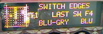
Turn on the game (if it was off) and use the buttons behind the coin door to enter "Switch Edges" mode. Switch edges shows a graphical representation of the switches in your machine. At this point you can even physically hit any switch on your machine and see how it responds on the dot-matrix display. Here is my switch matrix:
With all of the balls removed from your machine, your matrix should look pretty close to mine.
MOST SWITCHES: Dot = open switch & Square = closed switch
OPTO SWITCHES: Dot = Blocked opto & Square = Unblocked opto switch.
You can test the above by physically hitting a roll-over type switch, and then pass your finger up the left or right ramp to see how your finger blocks the opto switches on the ramp entrances. Your matrix might look different than mine above depending on the rotational state of your idol. The idol head uses 3 opto switches that "see" a spinning disk with a notch below the playfield to determine the position of the idol head. If my idol head is in a different position than yours, then the opto switches on column 9.
Q: But Garrett, my switch matrix has NO squares... they are all dots!!
A: Your playfield has lost the +12volts on the secondary +12 volt line. Remove the back glass and check fuses F115 and F116 in the upper left corner of the large power driver board. F115 is the primary +12 volt line and +F116 is the secondary +12volt line fuse. If the fuses are good, then check the +12 volt connectors at J116, J117 and J118 in the lower left corner of this power driver board. There should be a connector in each of the three. Make sure the wires are firmly in each of the three connectors. Notice the wires are black and grey-yellow. This grey-yellow wire is the +12 volt wire that supplies the optos. It's hard to say which of the three goes to your opto switches because if anybody has removed your power-driver board, then they could have arbitrarily plugged these three connectors in any combination since they are all three electrically the same. You can follow this grey yellow wire to all of the opto boards and even the ball trough boards. It would be great to have a volt meter to measure +12 volts on this line to help troubleshoot your problem.
Now, if you switch matrix looks like mine....
You can slowly roll a ball down the trough and watch it cause EVERY square on column 8 turn from a square into a dot. Now open the coin door and physically push up on the solenoid that would kick that ball onto the playfield. This will cause that "trough jam" opto to work. This opto only sees the ball as it gets kicked out, or if there are two balls jammed so they are sitting on top of each other at the right end of the trough.
You can fill up the trough completely, then remove the balls (I'm sure you can figure out how to get them out). Try this a few times to see if you can isolate 1 or more of the 7 squares not working properly.
Remove ALL balls from the trough. Close the coin door. Hit the flipper buttons to activate the flippers WHILE still in switch edges mode. Look for flickering square-to-dots on that column 7 trough switches. We're looking for flipper vibration causing intermittent flickering on the opto switches.
Another method of checking for vibration related bad optos is to bluntly hit the playfield near the flippers to see if the vibration from your fist can cause any squares to turn into dots.
Q: But Garrett, I can't find any problems, all 7 optos are working fine and I can't get any to flicker??
A: Later on this web-page I'll talk about a problem with the metal ball trough itself. Your opto switches might be okay and your trough is the problem. I'd still keep checking your optos for awhile to try to get one of those squares to flicker into a dot from vibration. Try opening the coin door and wiggling the wires that go to the trough boards or gently tapping the trough circuit boards with a plastic end of a screwdriver.
Q: I have all squares except that one is always a dot and never changes into a square!
A: This would describe a bad LED. If the LED is bad and not emitting any infrared light, then the switch will behave as if there is a ball in the trough. The phototransistor on the other opto circuit board cannot see the infrared light, so it thinks there is a ball in the trough, and it shows the switch as a dot and not a square. To verify a bad LED, shine a flashlight onto the other trough boards (while it's still mounted to the trough) and see how the presence of flashlight causes the dots to change into squares when the phototransistors on the other board sees the light from your flashlight. If the suspect bad LED switch now changes into a square when you shine the flashlight, then yes, you have a bad infrared LED, see my new web-page for acquiring replacement parts for suggestions on obtaining a replacement LED.
Remember, these LEDs are infrared LEDs and they do not emit light that we can see. Radio Shack does carry a special infrared detector that you can put in the path of the LED to see if it working but I never needed such a thing bad enough to buy one.
At this point I'll hope you found a flickering trough opto. I'll bet that it's one of the top 3 squares. The topmost square is the left-most trough opto. The bottommost square is the right-most "ball jam" opto on the opto boards. Now that we discovered the bad opto we need to repair it.
FIXING THE BAD OPTO
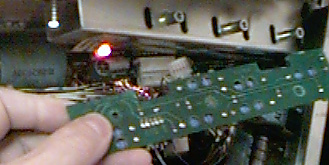
First we'll work on the easiest to access trough board... the one closest to the front of your machine. Lift and pull out the playfield a little until it "latches". You don't need to raise it up. There should be three screws holding the green circuit board to the trough. Remove them and unplug the 4-pin connector from the board.
Now keep in mind which square you detected the flickering. If it was the top-most square, then your problem is with LED7 or R7, if your bad square was the second square, the bad parts could be LED6 or R6, and so on.
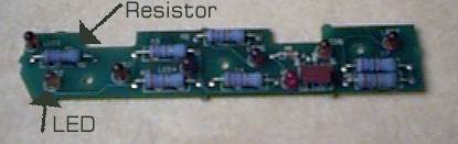
You'll notice there are only TWO PARTS for each opto on this board. Either the resistor is broken, or the LED is broken. The resistors are the big (usually blue) cylinder type parts with color bands around them. The LEDs are the nipple looking parts that protrude out from the boards (can you think of any other way to describe it?). I am willing to bet that you'll find the resistor has broken. If you wiggle it you'll notice that the little wires that come out of each end might be broken on one end.
If you can't find any broken resistors, then check the LEDs. Sometimes the led will break at it's base. If you didn't find a broken resistor then give the suspect bad opto's LED a good wiggling. If the wire is loose where it enters the base of the LED you should feel the LED is a little loose. Ordinarily, the LED is pretty solid and should not let you wiggle it around.
Q: I found a bad resistor, now what?
A: These resistors are rated: 270 ohm, 5%, 2Watt. The 5% means that the actual value of the part could be from 257 to 283 ohms. The 270 ohm is the most important part that you need to get in a replacement. The resistor is a 2 Watt. This is the LEAST wattage you could replace it with. Technically, you can replace it with a 270 ohm 7 Watt, or 10 Watt if that's all you can get. If the 270 ohm replacement resistor is physically larger then you could mount in on the opposite side of the board, just as long as one end touches each solder pad. This part can be installed in either direction.
I live in a medium-to-small size town and we do have a specialty electronic shop that carries these 2Watt 270 ohm resistors, so you might be able to find one where you live. Radio shack might have something that would work if you're lucky. On-line electronic sellers might have them too, but they probably have a minimum order. These resistors should cost around 25 cents (US) to 50 cents each.
A2: If you don't want to replace the resistor, then you could get away with blobbing some solder to "weld" the break together, but in my experience this doesn't last very long.
Q: My resistors look good, but my LED looks bad, it wiggled pretty loose like only 1 of the 2 pins is holding it on.
A: You need to replace that part. I'm not sure if Radio Shack carries these either. Williams doesn't show any part number for this LED, but what you want to look for is an "Infrared Light LED" that's physically this size. A regular LED that emits light that you can visually see will not work, it must emit infrared light.
LEDs are unidirectional, they should be installed in a certain direction. They usually have a flat end along the base. This flat side should line up with the flat side as drawn on the board where you put the LEDs in.
Q: I can't find a replacement LED or I really don't want to look all over for this part, what should I do?
A: The game usually functions pretty good with bad opto switches on the right side of the trough with the exception of the "ball jam" LED7. I would remove the bad LED completely and replace it with the LED from the one labled LED2 or LED3, and leave LED2 or LED3 empty with no LED. The game might act kinda funny once in awhile (like during 6-ball multi balls), but it should get you by.
Q: This board really does look okay, I can't find any problems.
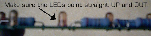
A: Make sure all of the LEDs are Clean. Sometimes a dirty LED will cause the flickering effect. Make sure that the LEDs all point straight OUT. Sometimes a slightly bent LED could be mis-aimed and cause problems...
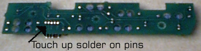
Sometimes when solder gets old and hot it can create intermittent connections on the circuit board where pins go through. You might want to check for cracks in the solder in the board and re-flow (add a tiny bit of fresh solder to) the pins on the board where the resistors poke through, the LEDs poke through, and the 4-pin connector pokes through.
Q: Argh.. I did all of the above but could not find anything wrong with this circuit board... now what?
A: Well, I have rarely had problem with the other board on the other side of the ball trough. I am NOT going to remove it from my machine for the creation of this web-page. It's not really fun to remove because I have to remove the right flipper coil so that I can remove the screws that hold the other board on.
If you are reading this because you have checked everything else out on this web page and are pretty much stumped, then you might want to remove that other board and check the "phototransistors" on that board. A phototransistor sort of looks like the LEDs on the first circuit board except they receive the light that the LEDs emit. Once in a great while a phototransistor will fail. Again, I'm not sure on a source for this part off hand and for now I would suggest replacing your questionable bad phototransistor with one from the far right end of the board (not the "ball jam" opto but the one right next to it). The game seems to work well with that far right side opto not working. Phototransistors are also unidirectional. You should see a small notch on the base of them to help you see how it is supposed to be inserted into the circuit board to match the notch drawn on the board.
Here's one more last ditch thing to do before removing that other circuit board...
With the first circuit board removed you can clean the phototransistors with a q-tip by poking it through the holes in the trough. If you phototransistors are very dirty, then this last ditch idea might help!
Q: Darn it! I have tried all of the above ideas...I can't find any "flickering" square in the switch test, the boards look good, but the game still spits out an extra ball or 2 for no reason during regular single-ball play!! What can I do now?
A: It's quite possible now, that your opto boards are just fine. Your metal trough is worn. Over time, as the balls fall into the trough, they cause little indentations in the trough. I've seen troughs that had a small indentation for every ball, so there were 6 little indentations in the metal where the balls usually sit. What happens, when a ball gets kicked out of the trough, the remaining balls sit in their indentations and DON'T roll down to the right by the force of gravity. This causes the game to see the fact that the left-most opto switch is still activated, so it tries to kick out another ball and the vibration from the kicking causes the balls to finally roll down and happen to hit that kicker which happens to kick an extra ball onto the playfield!
To solve this I usually remove the trough and use some thin files to file the inside of the trough where the balls sit so that the indentations are gone. With the trough in your hand you can sit a ball in it and very slowly elevate one end of the trough to watch the ball creep along the path in the trough and watch carefully for any place where the ball would rather sit in an indentation than roll down naturally. File away until the ball rolls unobstructed!
I hope that this web page has helped at least one of my fellow IJ owners! Email me
if you still can't figure out your problem. Please tell me what all you did according to the above instructions. Thanks!
ß Back to Main Indiana Jones Cleaning page.
ß ß Back to my home page.